e-Bus Charging Detailed Design
in Energy Transition, Discipline Engineering, Detailed Design
Share
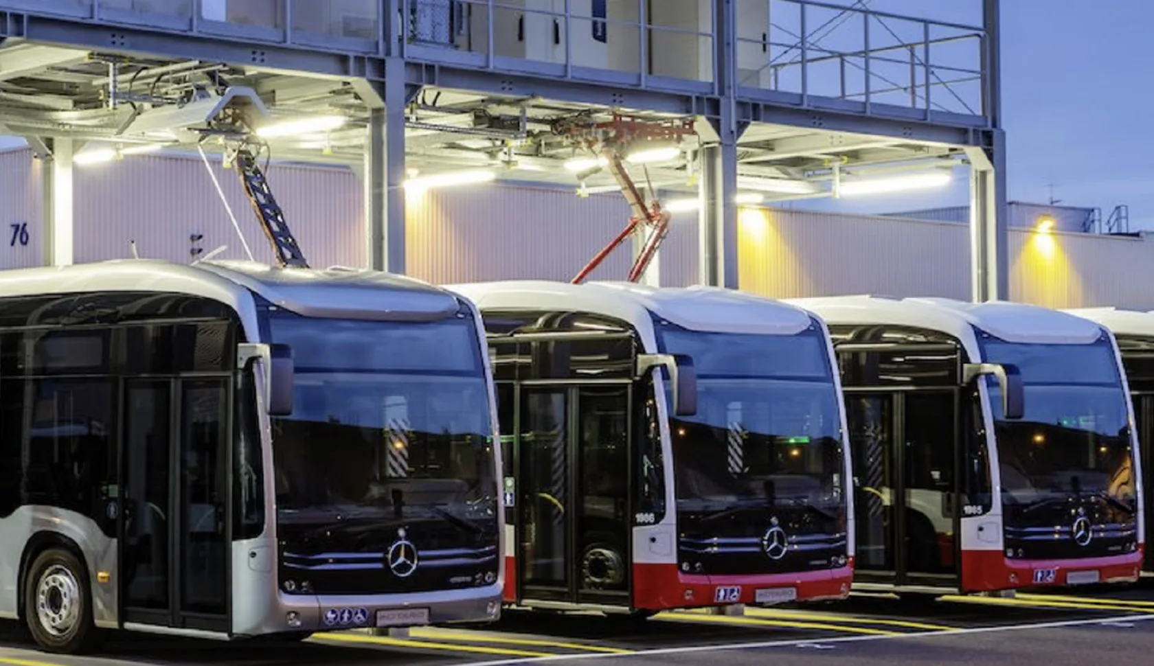
An e-bus end user had previously installed a new 11kV supply, 11kV/400V transformer and containerised LV panel to supply a series of sixteen chargers for their bus depot. OSL were engaged to undertake design for an extension to the installation to incorporate a further nine 80kW chargers for older model BYD buses.
OSL’s client provided the chargers, hub and software and oversaw the installation, commissioning and handover to the e-bus end user.
Project Overview
OSL's scope of work included:
- Maximum load checks and subsequent load calculations for adding the new chargers
- Calculation of new installation cabling, protective devices, fault levels, discrimination checks
- Earthing calculation and layout drawing
- Circuit protective device protection settings
- Designer’s Risk Assessment
- Layout / cable routing, including ladder rack views and weight calculations at key positions
- Cable schedule and Materials Take Off List.
Key Aspects of the Delivery
The delivery of the detailed design included:
- Site survey to discuss requirements, identify potential hazards, review site data and confirm installation methods
- Preparation of proposed load schedule
- Full Trimble electrical calculation model of the existing and new installation with agreed installation methods, circuit protective devices, and with specific protection settings to ensure suitability and full discrimination with upstream devices
- Earthing calculation to confirm minimum main earth connection for the new installation
- Designer’s Risk Assessment to identify design and installation hazards, then introduce control measures to remove, or reduce risk to an acceptable level
- Preparation of protection settings for ACB / MCCBs to ensure circuit breakers are set correctly to remove nuisance tripping / prevent inadvertent overloading
- Detailed equipment layout and cable routing, indicating minimum bend radii, loading of proposed cable containment, with maximum safe working loads for specified spans
- Cable schedule and Material Take Off to facilitate installation
- All documentation issued to the client for comment, then subsequent update and re-issued for use
- Regular communication with the client to identify any changes to the user requirements and ensure all queries are fully clarified.
Benefits to the Client
- All elements of the electrical requirements are covered, leaving the client to focus on their speciality work
- Complete detailed package of layout, single line diagram, cable routing and earthing drawings and documentation for the installation
- Comprehensive compliant design to ensure a successful installation, commissioning and handover to the end user.
Latest Case Studies
LNG Offloading Terminal Pre-FEED
IM Skaugen (IMS)
Centrica Storage - York Compression FEED
Centrica Storage
LAPS Compression Feasibility Study
A Gas Producer
LPG FEED project
Independent Oil and Gas Company
Pyrolysis Wax Plant Modification Design FEED
Trifol